This week I completed a lot of work on my robotics project. In last weeks blog posts, I detailed my initial thoughts toward my robotics project, and thought of the possiblity of making a robo-dog. After further consideration, I decided to make an ultrasonic sensor that maps out the surrounding area. This is a good project, as it has lots of applications for further robotics projects, and it is a project that pushes me to write more advanced C++ code. This week I was able to write most of the written report, design and 3d-print the body, and try to code it.
The report was mostly written around fitting the ultrasonic sensor into the task. I came up with the idea before defining the problem, or discussing the possible solutions. Working backwards made writing the report easier, as I knew exactly where I was trying to get with it. I used the problem of the difficulties of cave mapping, and proposed the ultrasonic sensor as a fast alternative to traditional methods. Coming up with the idea before hand was fine due to the vagueness of what problem we had to solve, but in a report that defines the problem for you, this would not be ok.
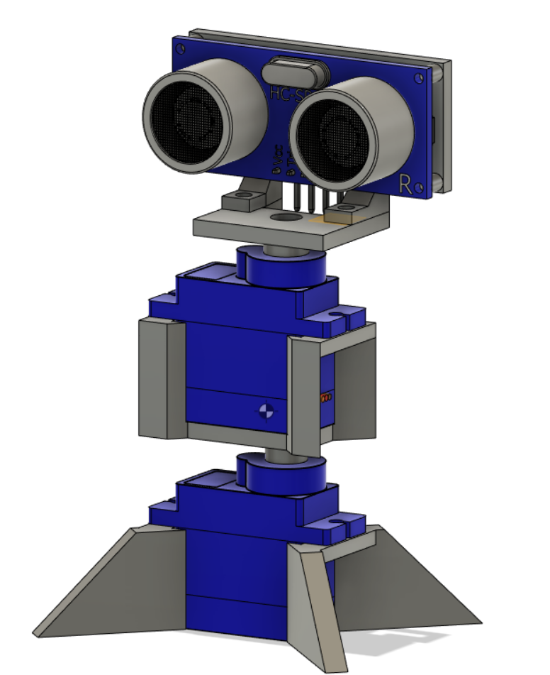
The design was annoying because the school only has 180 degree servos. This means to map the full 360 degrees, I would have to use two servo motors stacked ontop of eachother. This posed an interesting design challenge, which I somewhat succeeded in. I succeded in the servo dimensions, the alignment of the rotation and most of the mounting. I failed in getting the parts to spin. As fdm 3d-printers are not as precise as injection molding, the servo motor teeth cannot be printed. When I made the design, I instead made the parts screw into the servo, thinking that they would rotate. When tested, the screw does not hold the two parts together strong enough to spin. I am considering sacrificing a screw, and just using super glue, but I will think about this further over the coming week. My design is below.
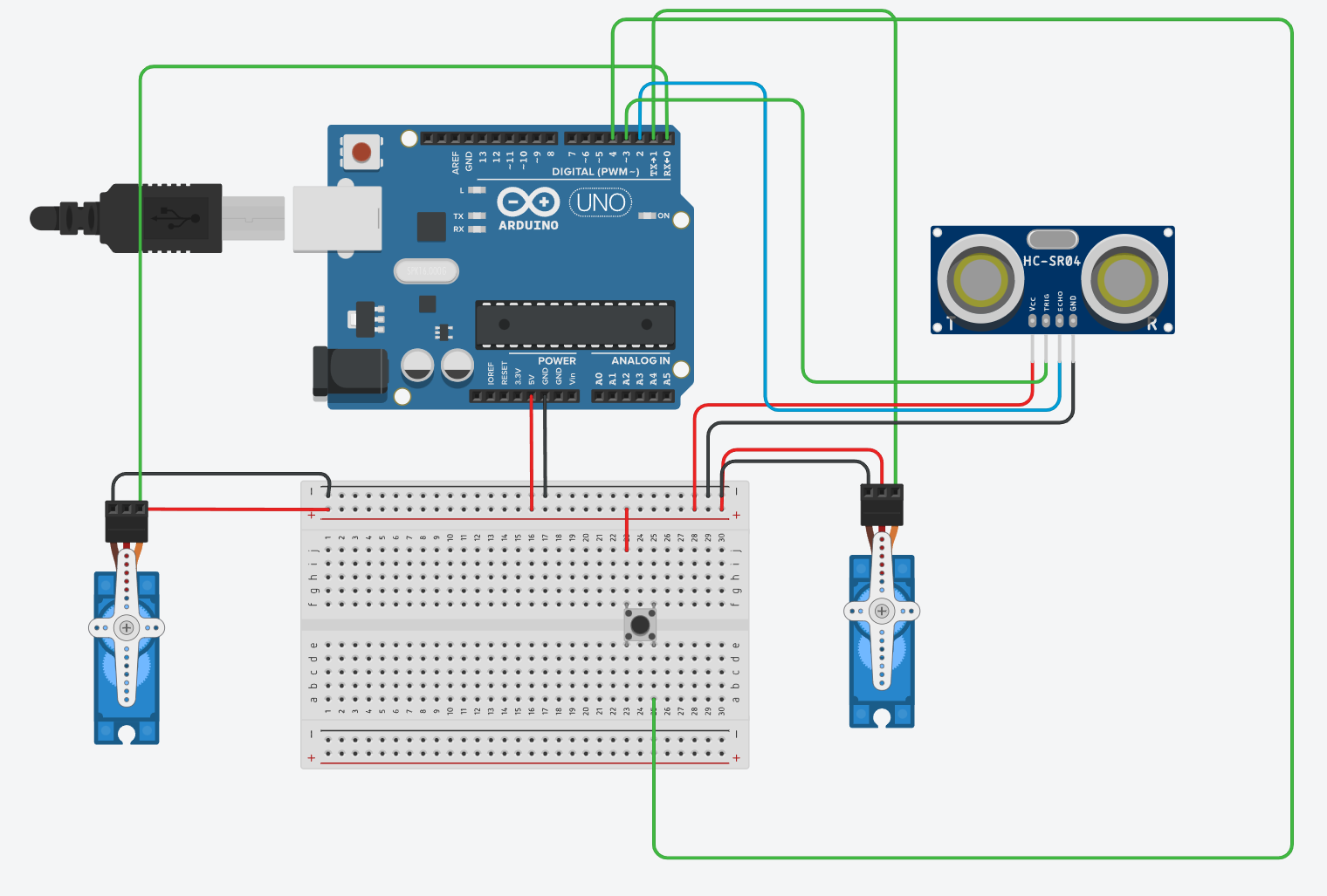
Using the Tinkercad simulation software, I had a go at coding the circuit. When I was coding it, I though that it was going to work fine, but there was a lot of errors. As I do not understand C++ that much, I managed to mistake char as a string. This meant there were many errors involving string and char conversion, however I do not fully understand what a C++ string is. There were more errors surrounding functions on top of this. I did not have the time to debug those errors this week, but it will certainly be done by next weeks posts. A picture of the simulator is below.