
Work I Completed
This week in robotics/mechatronics, I completed the challenge on bit maths. This challenge involved setting up an array of LEDs representing individual bits, and changing them corresponding to the bit math completed by the Arduino. Although not completely necessary, a shift register was used to turn three PWM inputs into the eight required for the LEDs. The bitwise operations used were AND, OR, and XOR, each comparing a binary number specified in the code, and a decimal defined as a serial input. The task explained how each operator works, which I have learnt in the past, and explains how a shift register works. Since I already know bitwise operators, I will be discussing how a shift register works.
Shift registers store a byte of data and parse that data through 8 output pins. These outputs can be manipulated by changing their bit values to high or low, it is called a ‘shift’ register, because the bits are manipulated by shifting their values. When a new 8 bits of data need to be put into the register, the bits gets shifted until there is 8 new bits in the register. On a smaller scale, a shift register is comprised of a series of flip-flops, with the output Q connected to the input of the next flip-flop. When the clock cycles, the outputs of each flip-flop are given to the input of the next, causing the bits to shift. A diagram of this is below.

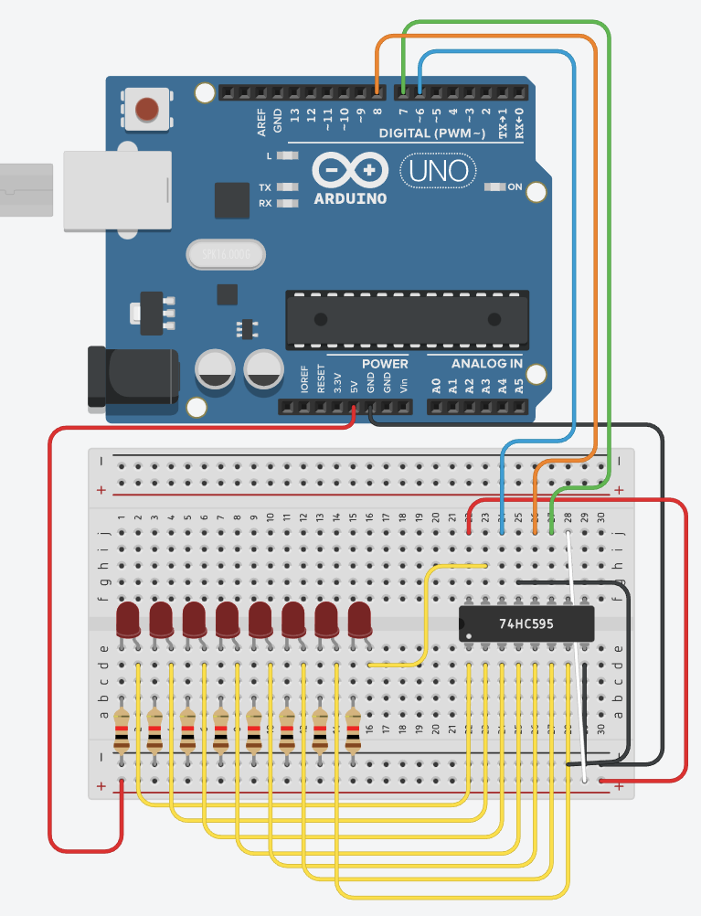
After this shift occurs, a latch pin recieves an input, telling the shift register to output the shifted bits. In my circuit, these bits shift to the output of the bitwise operations, and output to the 8 LEDs. This is depicted in the circuit below - the yellow wires are shift register outputs, the blue wire is the shift register input, the orange wire is the shift register latch and the green wire is the shift register clock.
I did not code the final solution for this challenge, however the valuable information was not within the coding. I already knew most information on bitwise operators, what I needed to learn was shift registers. Evidently shift registers can be very useful when using many outputs, and understanding how to use them properly will help me in future. It would be interesting to see whether shift registers could be manipulated into having PWM outputs, as fundamentally PWM just turns a signal on and off. Doing this would greatly increase the shift register functionality, especially considering shift registers have seperate 5v input, meaning a seperate power source could be used to run several motors.
Reflection
Did you come to class prepared to learn, in both your attitude and with all your supplies?
As usual this week I arrived to class with all my supplies, but I believe my attitude as of lately has not been so great. This week I should have had time to complete more mechatronics/robotics work, as one challenge is not enough for the whole week. Instead of doing my assigned work, I was helping piers with their work, talking, and doing the NCSS Challenge. This is not inherently bad, but becomes a problem when I have not completed enough work to write these reflections.
What can I do tomorrow to help other learners more?
As understanding shift registers was not the primary objective of this challenge, I will be able to relay what I have learnt to the other robotics/mechatronics students, and it may be of some use to them. They will benefit just as much as I will from this information, so it is important to help them understand it if they need to.