
This week I completed the object-oriented programming (OOP) logic gate simulation challenge. There was a massive difficulty spike between starting, and finishing this challenge. I thought understanding the given code was the hard part, but far from it. As there are many steps, I will summarise the process. I had to understand an article explaining how to turn a written circuit into a diagram, a 7 step process requiring me to learn Karnaugh maps. I had to code a JK flip flop using a Karnaugh map formula, and finally create the circuit diagram in the simulation.
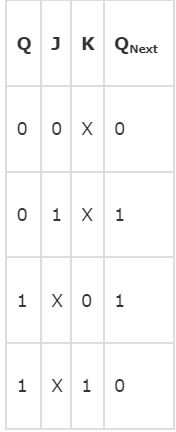
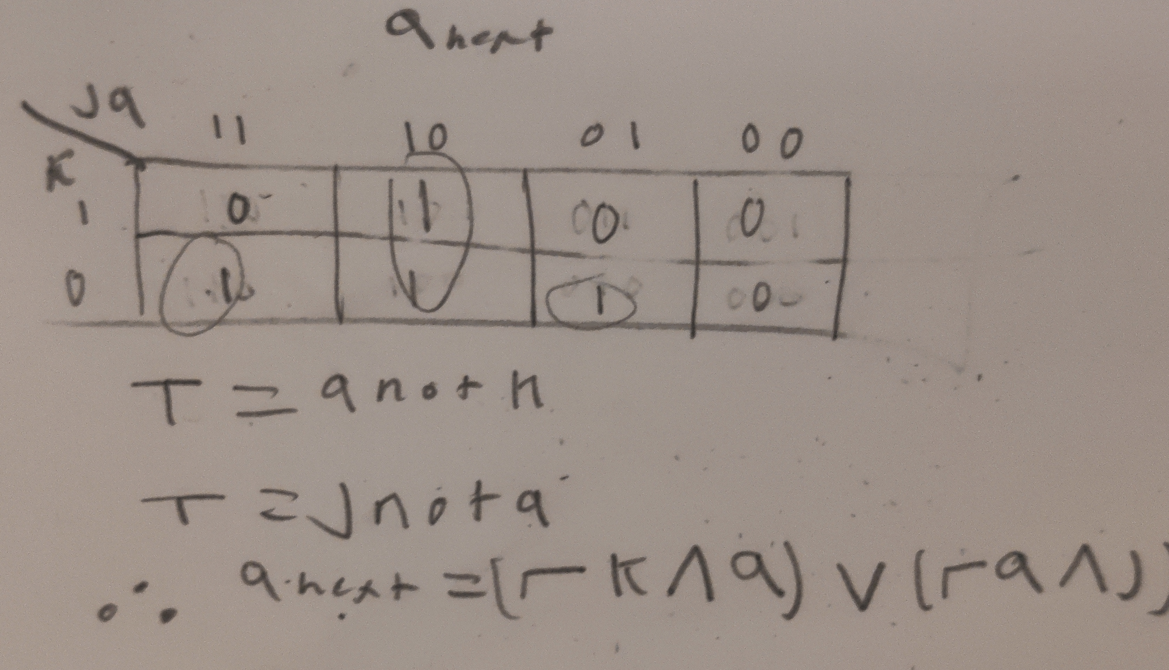
Understanding the article was difficult, but it proposed a very compelling way of creating a circuit diagram - finite state machine, truth table, Karnaugh map, formulae, circuit diagram. The idea of a Karnaugh map is especially exciting to me - an easy way of creating a boolean algebra formula. Learning the 44 boolean algebra laws is not appealing for me. I used a Karnaugh map to determine the formula for a JK flip-flops next output, and used this formula in the JK flip flop class. See below:
 --> -->
|
|
| JK Flip Flop Qn+1 Truth Table --> | JK Flip Flop Qn+1 Karnaugh map |
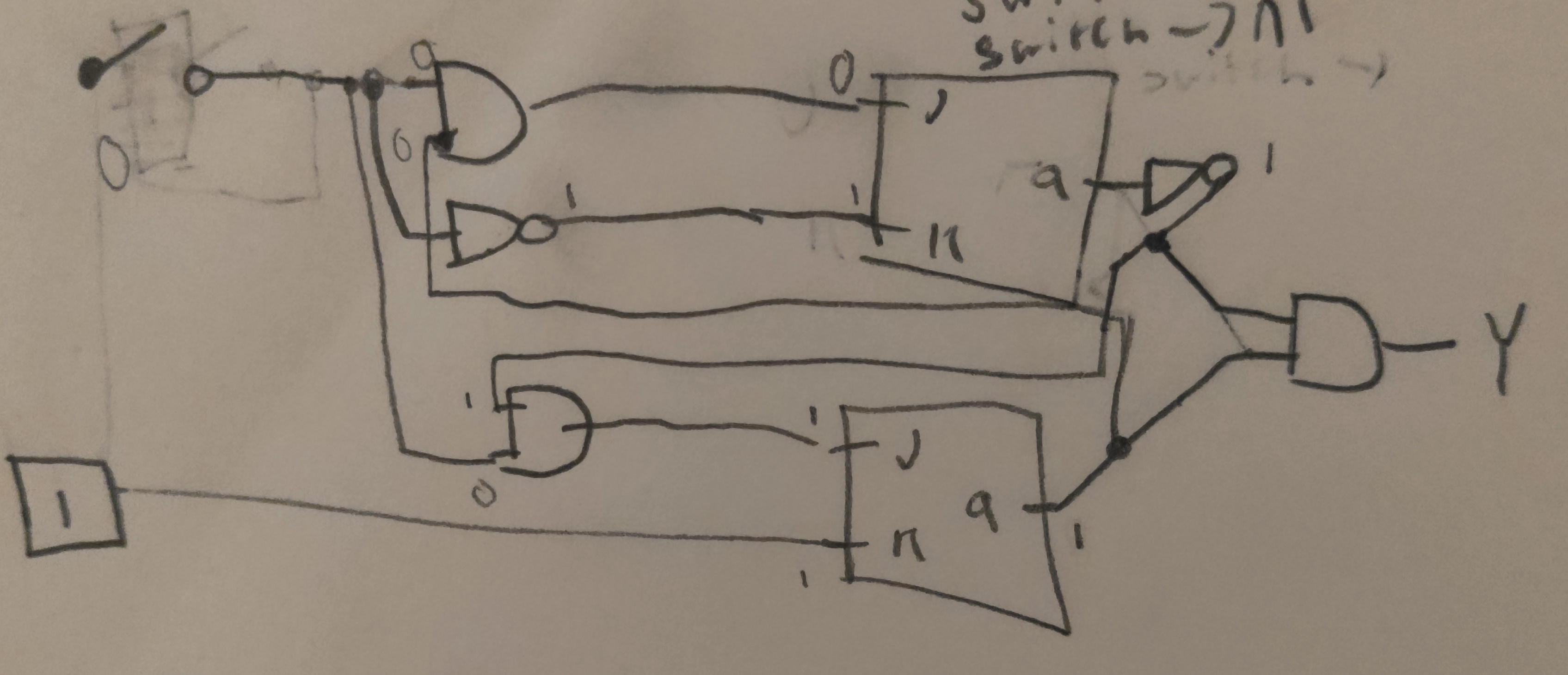
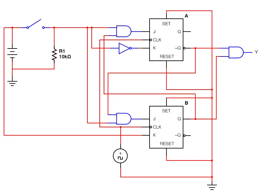
Removing all the unnecessary parts from the circuit was difficult. I had to find what the power sign was and what side was positive and negative, getting this wrong would ruin the circuit, and I kept second guessing myself during troubleshooting, making this challenge take more time. In the end, K of the second JK flip flop was hooked up to a constant power source, and the switch affected the other inputs. See the diagram below:
|
|
|
| Starting circuit (All Circuits, n.d.) --> | Remade Circuit |
 -->
--> Creating the circuit at the end was the hardest part. Creating connectors, and the basic circuit was simple, but the output was always the same. After hours of troubleshooting, I found two issues - I used or-gates instead of and-gates (not proud of that one), and the JK Flip Flops were moving to the next output before the next cycle. This took what felt like hours to find, and there was a comment in the challenge document that led me straight to it. Very frustrating. The clock cycle loop is below.
while True:
    button_press = int(input("Button Pressed? "))
    if button_press == 1:
        switch.switch = 1 # Set switch input to 1 for all 3 passes.
    else:
        switch.switch = 0 # Set switch input to 0 for all 3 passes.
    print(y.getOutput()) # Run the circuit, and display the output.
    # Change q to the next cycle, and allow a new Qn+1 value to be generated.
    jk1.visited = False
    jk1.q = jk1.next
    jk2.visited = False
    jk2.q = jk2.next
It was very satisfying to successfully combine all the areas of computer science I have been learning in the past few weeks. I should now be able to create a circuit from scratch with a different worded problem - maybe a challenge for next week? I think doing this would consolidate the knowledge and process covered in this challenge - I completed the circuit, but my hand was being held the whole time. To take it further, I could turn it into a physical circuit in mechatronics, using an Arduino to simulate logic gates.