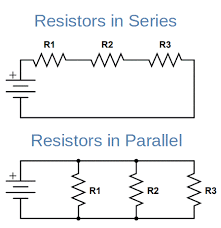
This week in Mechatronics, I completed the assigned tasks about the fundamentals of electricity, and Ohms law. After the completion of these tasks, a classmate and me was able to do the maths for the effect of resistors in succession, and resistors in parallel.
The fundamentals of electricity task mainly required me to read, and remember - no exercises were involved. The content discussed the flow of valence electrons, the catalyst for this flow, and the measurement of this potential catalyst. Valence electrons are allowed to flow from atom-to-atom, as electromagnetic attraction between the electrons and protons is weakest in the outer shell. This means that a catalyst contains enough force to push a valence electron into another valence shell, causing the original valence electron to also get pushed. This catalyst is almost always a build up of electromagnetic force from detached-groups of protons and electrons trying to get to each other. The quantitative charge that could be produced from this is called electric potential. Electric potential is measured in volts, but it is not to be confused with voltage, or difference in electric potential (which is also measured in volts). Voltage defines the amount of work needed to move an element from one position to another. This is all very confusing, and is not at all an extensive comprehension of electricity, however it is beneficial to understand the basics as a foundation for future work. The work I am doing at the moment does not require this knowledge, but future work may.
Ohms law is very easy, it is a simple formula - voltage = current * resistance. This can be easily rearranged to determine the missing variable. Ohms law in practice is also simple, for a circuit with a known voltage and resistance, first find the current, and then find the voltage at any point in the circuit. This is beneficial to find the voltage after a specific resistance, so the proper resistance can be applied to every component in the circuit. I will certainly be using this in my upcoming assignment where I will need to design my own circuit.
My classmate and me were able to do the maths for 1k Ohm, and 220 Ohm resistors running in succession and parallel. The maths for running in succession is easy - the resistance is simply added together, which is used to calculate the current. After this, the current can be used to find the voltage after each resistor, and from memory, both resistors subtracted 2.5 volts from the original 5. We were able to test this with an Arduino and multimeter, and the maths was accurate. Resistors running in parallel adds an extra step - the inverse of the two resistances are added together, which equals the inverse of the total resistance, kind of like Pythagoras. With this resistance, the current can be found, and then using Kirchov’s law to split the current in half, the voltage at either resistor can be found. We tested this, and it ended up being 0 volts on both resistors, which was confusing at first, but I later came to realize that voltage at the negative terminal is always 0. Whilst trying to test the circuit, I also burned 2 LEDs by accidentally shorting the circuit, which was a little frustrating. I did not get an image of these circuits, but an image distinguishing the two circuits is below.

(Electronics Reference, 2022)
That aside, it was fun to test these circuits, and see the physics work in reality. It is great that I can design, and simulate resistance on circuits properly now, as this is a fundamental of circuit design I was not capable of. This will become more useful as I continue to create more complex circuits without any guides.
