What I have been doing
This week in robotics / mechatronics I was essentially given free rain to do research for my project in term 2. In year 11 I missed a significant amount of term 4 due to ilness and was unable to complete my planned project on stereo vision. Considering this, I thought it would be best to continue on with stereo vision this year, as it could culminate into a very impressive final project. I have previously discussed my plans for stereo vision in this blog, however there are more requirements in the new practical project meaning I will have to alter my plans slightly.
Originally I was looking to create a stationary camera system that could map out a 3d environment by measuring the relative location of objects, and turning those points into 3d geometry. The new practical project task requires some physical interaction with the real world, like with a motor for example. My plan is to extend the stereo vision into a practical application - a computer vision rover comes to mind first, however it could be something as simple as a servo that can accurately hit a button. This will be something that I can look into next term, as the stereo vision system will be extremely similar in any practical application.
How distortion correction works
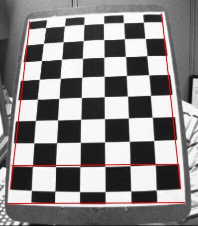
As with most “solved” problems, there is seemingly endless research into correcting lens distortion. Deciding on a method is difficult as distortion correction is a large factor into the success of a stereo vision system. There are many types of distortion, however the major two are radial and tangential distortion. Radial distortion causes straight lines to appear curved, becoming larger at father points from the image center with positive radial distortion, or the opposite with negative. This effect is highlighted in the below image where the straight red lines do not line up with the radially distorted checkerboard lines.
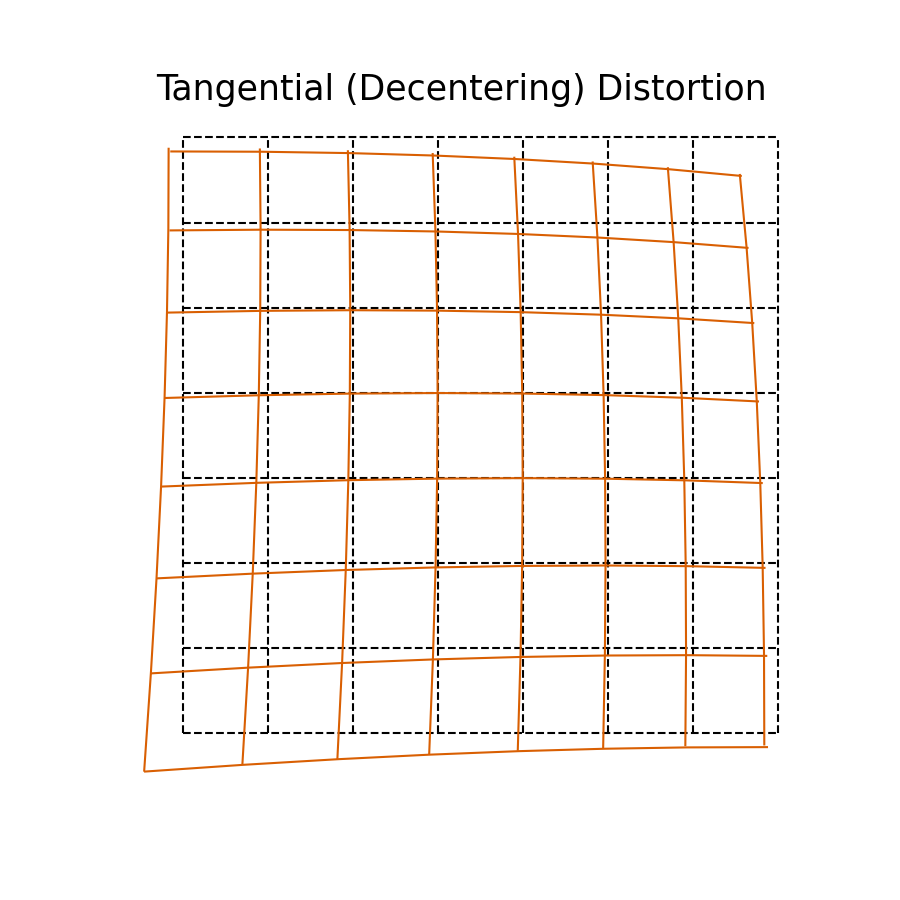
Tangential distortion is commonly associated with the de-centering of an image plane, i.e. where the image is skewed from its regular positioning. This is highlighted in the below image where the yellow image plane is skewed from the grey plane.
These distortions are defined by functions of x and y in the below formulas:
Radial Distortion
\[ x_{distorted} = x( 1 + k_1 r^2 + k_2 r^4 + k_3 r^6) \]\[ y_{distorted} = y( 1 + k_1 r^2 + k_2 r^4 + k_3 r^6) \]
Tangential Distortion
\[ x_{distorted} = x + ( 2p_1xy + p_2(r^2+2x^2)) \]\[ y_{distorted} = y + ( p_1(r^2+ 2y^2)+ 2p_2xy) \]
So to be able to calculate the tangential and radial distortion and hence reverse it, 5 paramaters need to be found which are called the distortion coefficients. These can be seen below.
\[ Distortion \; coefficients=(k_1 \hspace{10pt} k_2 \hspace{10pt} p_1 \hspace{10pt} p_2 \hspace{10pt} k_3) \]
These coefficients are found by taking several images of a pattern (typically a checkered board), finding the corners of each box pattern and then calculating the disparity between the cameras image, and the real world difference. When considering the image to be flat (i.e z=0) if each box is an equal size, however there are different numbers of captued pixels in each box, this disparity can be calculated via the distortion coefficients.
Fortunately instead of doing these difficult calculations, the opencv python library has a method for handling it. First the corners of the pattern must be found with the below function.
ret, corners = cv2.findChessboardCorners(image, (gridx, gridy), output_corners)
If this function returns corners (described by bool ret), their location can be refined with the below function:
ref_corners = cv2.cornerSubPix(image, corners, winsize, zeroZone, criteria)
With this data, the camera matrix, distortion coefficients, rotation vectors and translation vectors can be found with the below function:
ret, mtx, dist, rvecs, tvecs = cv2.calibrateCamera(objpoints, imgpoints, image.shape[::-1], None, None)
Objpoints is a list of xyz coordinates relating to the checkerboard where z is always 0, i.e [(0,0,0), (1,0,0), (0,1,0) … (patternx,patterny,0)]. Imgpoints is the previously calculated list of corners.
A refined cameramatrix can be created on a per-image basis with the below function:
alpha=1
width, height = imagew, imageh or img.shape[:2]
cameramatrix, roi = cv2.getOptimalNewCameraMatrix(mtx, dist, (width, height), alpha, (width, height))
Now finally with all these variables found, the image can be undistorted with the below function:
undistorted = cv2.undistort(image, mtx, dist, None, cameramatrix)
Unfortunately during this week I have been unable to obtain a flat checkerboard pattern to test this undistortion. I should have time to do this over the next few weeks so I can move onto Harris Corner detection / some other form of feature detection.
Reflection
Would you consider creating your own code for distortion correction?
Distortion correction is a very complicated topic with many professionals focusing only on improving it. Based on the complexity of the topic and my tiny prior knowledge surrounding cameras, if I were to code my own implementation, it would likely be very basic and hence perform worse than just using OpenCV. My current goal is just an archetypal stereo vision system, and I will try to improve its functionality and accuracy later, after I have a decent baseline understanding of the topic.
What are your next steps?
After I test the distortion correction with my camera system, I will move onto feature detection algorithms. Harris Corner detection is one of the most iconic of these algorithms, and would be fairly easy to understand and write code for, however it is long outdated. After some research I will decide if I want to do a better, but more complex algorithm.


