
What have I been doing?
As previously discussed on this blog, I am in the process in creating the computer vision system for W.I.N.S.T.O.N the robot dog. Quite naively, I previously approached this by looking through various Wikipedia articles and randomly choosing an approach to map Winston’s environment. My research into this approach can be read on this blog. The approach I happened upon was not suited to this robotic dog application for a few reasons. Over the past week I have been working on fixing these issues.
Sparse v.s. Dense matching
There are two ways to approach finding correspondence in the stereo images, sparse and dense. Sparse correspondence matches a few distinctive features between the stereo images, whereas dense correspondence aims to match each individual pixel between the stereo images. My previous approach to the correspondence problem was to use harris corner detection to find matching corners between the two images. This method is considered a sparse matching method, as it matches a few distinctive features i.e. the corners. Sparse correspondence does not apply very well to Winston when you think further into the project. One of the goals for Winston is to traverse/avoid difficult terrain. To be able to do this a high resolution 3d model will have to be created to ensure that the terrain that Winston wants to traverse is actually there, and is represented properly. Sparse correspondence provides a very low resolution 3d model, as there are significantly less points to work with, and bold assumptions would have to be made surrounding how points connect to each-other. A dense correspondence approach provides depth at the pixel level, meaning there will be significantly more information about the terrain. Additionally, the correspondence at a pixel level can be converted directly into a height map meaning there is no need to make assumptions about what points connect together.
Depth Calculations
Previously as discussed in this blog I was using a method for depth calculations called multi-view geometry. This involves the use of a number of matrices to determine the depth of an image, and is discussed further in this blog post. This method essentially does a calculation of distance using the internal camera parameters of both cameras, and then estimates the intersecting point of both distance vectors to get the real-world distance. It is a very complex method, involving a number of camera concepts I do not understand - I would just be plugging in the formulas and hoping it works. In light of this, I have decided to use a different method which is much closer to basic triangulation. This means I can fully understand how the method works and can make changes / optimisations as I implement it. This method uses simple trigonometry to relate the corresponding x coordinate on either image plane to depth of the object being captured. See the below diagram:
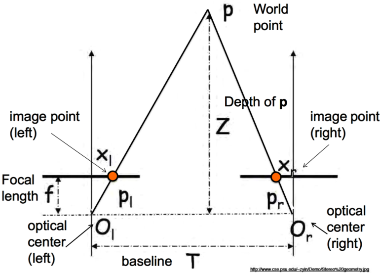
Note that \(x_l\) and \(x_l\) represent x pixels from the leftmost pixel of their respective images.
The formula between depth and the image x coordinates is made by creating similar triangles. Note the highlighted triangles in the below diagram:
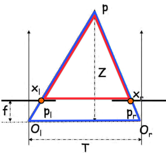
The base of the red triangle (\(T_1\)) is defined as:
\[T_1 = T + x_r - x_l\]
This was hard for me to grasp conceptually, so I expanded the equation. If you look at the diagram \(T_1\) is the same as \(T\) minus the left and right distances between the optical center, and the image point, therefore if both images are \(n\) pixels wide:
\[ \displaylines{T_1 = T - (x_l - \frac{n}{2}) - (\frac{n}{2} - x_r) \\ = T - x_l + \frac{n}{2} - \frac{n}{2} + x_r \\ = T + x_r - x_l} \]
The height of the red triangle (\(z_1\)) is defined as:
\[z_1 = Z - f\]
If two triangles are similar (these triangles are), the base to height ratio will be equal between both:
\[ \displaylines{\frac{T}{Z} = \frac{T + x_r - x_l}{Z - f} \\ \frac{T(Z-f)}{Z} = T + x_r - x_l \\ T - \frac{Tf}{Z} = T + x_r + x_l \\ -\frac{Tf}{Z} = x_r - x_l \\ \frac{Tf}{Z} = x_l - x_r \\ Z = \frac{Tf}{x_l - x_r}} \]
All variables in this new equation for Z can be found, meaning Z can be found.
The issue with this formula is that the units do not match up. The baseline (\(T\)), and focal distance (\(f\)) is measured as real world distance, not camera pixels. This means to use this formula, a conversion has to be made. This is done by determining the physical size of the camera sensor, and using that to determine the physical distance between pixels which can be used to convert pixels to distance. I have previously discussed distance between pixels as the distance between real world objects represented by pixels, but in this case I am referring to the actual distance between pixels on the surface of the image sensor.
Reflection
Am I staying on track to complete Winston?
This week has been a little difficult in terms of working on Winston. I was meant to submit project definition documents for both robotics and data science last week on Monday, but I did not have the time due to me being away from school and hence only finding out about the documents the Sunday night before they were due. This put me into a bit of a slump when it comes to working on Winston, as whenever I had the chance to do some work I had to do the project definition documents. Even after a week has passed, I still have not done a significant amount of work on them as it is quite monotonous work. I would rather be learning stuff - I will make a big push to finish them tomorrow, so I can continue creating Winston’s vision systems.