
What I have been doing
In the past week or so I have been able to create the stereo camera housing for Winston. I have covered several software topics surrounding Winston’s computer vision systems on this blog, but I have not yet discussed the physical design of the vision systems. I designed the housing with CAD software (Fusion 360), and then 3d-printed the designed components. I loosely followed the design process while creating this.
Design Requirements
The requirements of the housing require a bit of explanation. In a stereo camera array, it is usually best to only displace the cameras either vertically or horizontally. This is because at the stage of block matching pixels, complexity will be linear instead of quadratic. When the cameras are only displaced horizontally, you can assume that the pixels of the image are only shifted in the x direction. This means for each pixel in one image, you only have to compare it to every pixel in the corresponding row, versus comparing each pixel of one image to every pixel in the other image. If you assume the image to be \(n*n\) pixels, displacing the cameras horizontally yields \(O(n)\) complexity, versus \(O(n^2)\). Considering this, the design of the housing should keep the camera sensors at the same relative depth, and displace them either vertically or horizontally.
The other requirements of the design are more simple.
- The camera sensors must not be allowed to move within the camera housing, as triangulation and pathfinding assume a constant relative camera position.
- A good distance between each camera’s optical center (baseline distance) is the average distance between the human pupils which is approximately 63 mm. The design of the housing therefore needs to make the baseline distance close to 63 mm.
- The camera housing must attach to Winston’s chassis in a way where the cameras are unobstructed by Winston’s body, and the camera housing maintains a constant relative position on the chassis.
Ideation
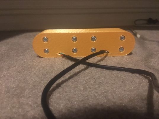
Due to the rigid design requirements, the design of the camera housing cannot differ much from a functionality standpoint. The one comparison I had to make involved the mounting of the cameras. As pictured in the below image, the cameras seem to have 4 mounting holes, presumably made for bolts.
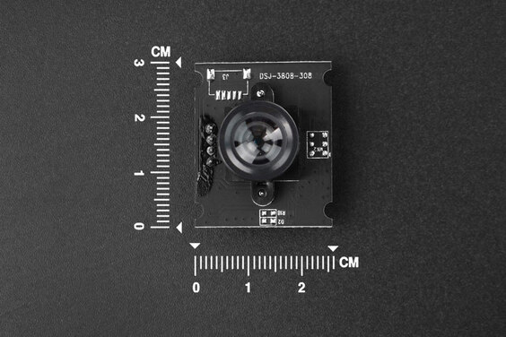
Unfortunately, these holes cannot be used as there are electronic components on the backside of the board that would be tensioned against if the camera were to be bolted in. Realising that this idea wouldnt work, I thought of a different solution. This was to create a hole that the PCB could slot into with a small opening in the front for the camera lens. An additional component would slot into the hole and be bolted in place, sandwiching the camera PCB, so it cannot move. See the below for my original sketches of this design (what an artist):
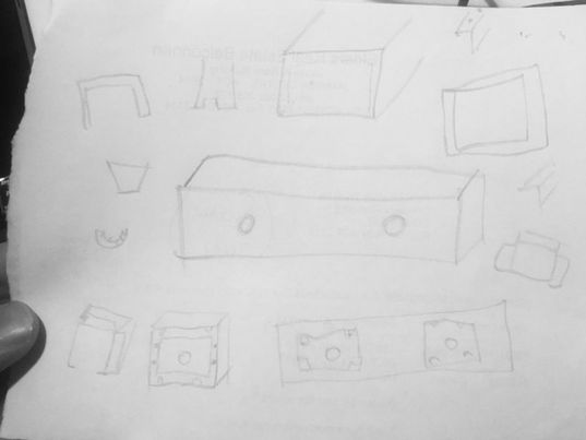
Specifically note the bottom row of sketches, as they detail the hole for the camera PCB, and mounting holes for bolts. This is the design I went with in the end.
Modelling and prototyping
My final model can be seen below:
The modelling was fairly straight forward, however I did run into some issues in the first printed prototype. Due to the size of the filament being extruded in FDM 3d-printing, the dimensions specified in modelling are usually 0.25 mm larger for each side. This means when modelling components being 3d-printed, you need to compensate. For example, a circular hole would need to be 0.5 mm larger in diameter to compensate. I did this correctly in the first prototype i.e. everything fit together, but the bolts would not tap into the plastic because it was too wide. This meant the mounting was loose, and not adequate. In the second prototype I reversed the compensation, and the result taps much better - but I think the holes could be slightly smaller still. The only other change I made was to make the cable opening smaller for aesthetic purposes.
During modelling, I also decided to make the back cover that sandwiches the camera PCB slightly shorter. I did this because it provides room between the back cover and the camera PCB for foam, so that the cameras are not damaged when they are sandwiched. This worked perfectly in the first prototype - sufficient pressure was applied to both cameras.
Final product (for now)
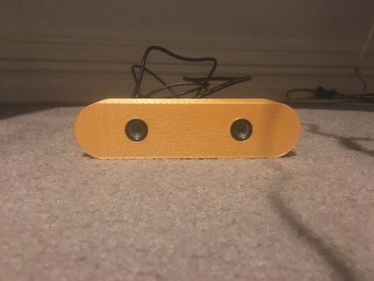
The final printed version can be seen below.
| Front View | Back View |
 |
 |
Note that this prototype has no way to mount onto the chassis of Winston, which is something I will add when my peers are ready.
I am happy with the aesthetics of the final product, however I am yet to see how it looks when mounted on Winston - the curved edges could look bad if there is material under the curve. Aesthetics is not nearly as important as functionality however, and I am also happy with the functionality. The mount is solid, optical centers of the cameras are exactly 65 mm apart,
Reflection
Do you have any strategies to not get overwhelmed this semester?
Yes. My ATAR estimate was not at the ~96 I need to get into UNSW co-op, so I no longer have the option to get overwhelmed and get exemptions from assessment items. I think this is a good thing as it locks me into the stress. Over the past year I have been trying to find how to make myself work hard again, and as bad as it sounds - stress is the best motivator, so having a way to relieve it without doing the work is counter-productive. Granted, it is still not good to get overwhelmed, so my strategy is to only allow myself to be stressed about things happening in the day, not the week or month. This also means I can feel good about what I have done in the day, and allow myself to have a guilt-free break once I finish my work. I suppose I will see how it goes and provide an update next week.